
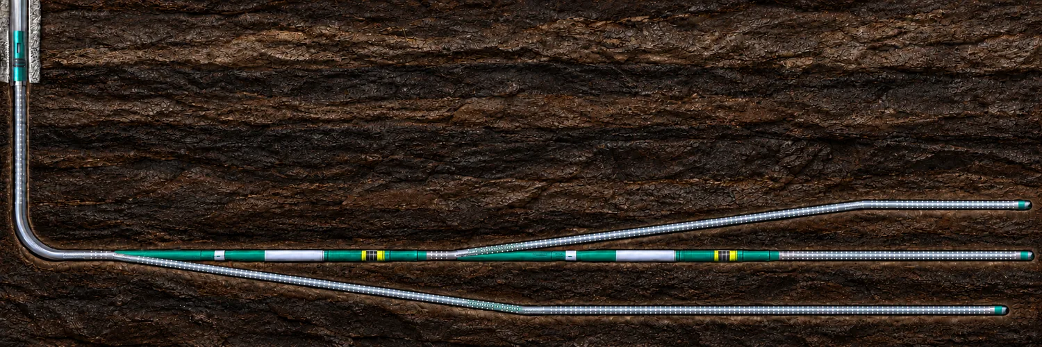
A horizontal well replaces a point of reservoir contact with a line. In low-permeability, heterogeneous or contact-limited reservoirs, one line may still be insufficient. A trilateral architecture extends the same development logic: retain one motherbore and add reservoir branches only where each branch creates useful contact that can be produced and managed.
A documented three-wellbore architecture
The field reference used for this engineering review combines a parent bore with two successive laterals. Each departure is established from a repeatable anchor/orientation reference. Slotted liners or screens, open-hole anchors, hydro-mechanical packers and production whipstocks form the documented completion basis. The reference is supplier-documented field material and is not presented as a BROT-executed well.
Disclosure boundary. Installed liner footage is not presented as total drilled footage or effective reservoir contact. Exact whipstock, anchor and packer setting intervals, orientation values, BHA configuration and installation sequence remain part of the engineering execution record and are intentionally not reproduced.
Why the third bore needs a reservoir reason
A trilateral should add more than branch count. The development case should show why a third flow path is better than a longer single horizontal, a bilateral completion or another well.
- Reach separated or heterogeneous targets from one upper well.
- Increase drainage where matrix productivity is insufficient for a single horizontal.
- Share casing, top-hole construction and surface infrastructure across several reservoir branches.
- Reduce surface footprint or slot demand where additional locations are constrained.
The same logic can appear in coalbed methane, heavy oil, heterogeneous gas-condensate reservoirs and offshore developments, but the architecture must still be screened for stability, flow allocation, solids, artificial lift, intervention and lifecycle access.
Construction logic — without publishing the execution recipe
1 · Establish a reference
Land the lined completion and establish the anchor/orientation reference for the next departure.
2 · Create the next departure
Deploy the production-whipstock arrangement and prepare the open-hole departure from the known reference.
3 · Drill and line the branch
Drill the lateral with the selected directional system and install the required liner or screen completion.
4 · Repeat only if justified
Establish the next reference and add another branch only where the reservoir and economics justify it.
The engineering control is repeatability, not a particular published angle or trip count. The source case lists seven construction stages, but that sequence is not the entire well programme and should not be misrepresented as a complete three-trip trilateral operation.
Production whipstock: a completion function, not just a drilling tool
A drilling whipstock mainly creates a departure. A production whipstock remains part of the completion architecture after the branch is created and can provide the intended flow path through the junction arrangement. That does not automatically establish permanent hydraulic isolation, selective re-entry into every branch or lifecycle pressure integrity. Those are separate requirements.
Independent operator evidence: Sibneftegaz / Tyumen Petroleum Research Center
A separate operator and research-center presentation, Application of multilateral well-completion technology at Sibneftegaz assets, was presented at the IX Rosneft Practical Seminar in Moscow, 29 September–1 October 2021. The author team included A.I. Farkhetdinov, S.V. Bondarev, A.E. Gilmutdinov and D.O. Kanygin from Sibneftegaz, together with S.Yu. Nimchuk, A.Yu. Orlov, I.A. Kunakkuzhin and P.A. Mashoshin from the Tyumen Petroleum Research Center.
The field-development record was subsequently expanded in the 2022 technical publication Development of multilateral drilling at Beregovoye field by Nimchuk et al. The follow-on paper provides additional context on the evolution of multilateral drilling at Beregovoye and the comparison of well productivity and startup performance. It is used here as corroborating operator/research evidence and is not treated as validation of the separate supplier-origin trilateral hardware architecture above.
The operator case addresses heterogeneous, thin productive intervals where additional standalone wells were unattractive. It documents a bilateral multilateral configuration with two approximately 500 m branches and liners/screens in the main bore and lateral. It is therefore independent evidence for the development logic of TAML 1, but it is not the trilateral architecture shown above.
| Parameter | Projected 1,000 m single horizontal | Actual multilateral startup |
|---|---|---|
| Gas rate | 430 thousand m³/d | 1,911 thousand m³/d |
| Drawdown | 2.90 MPa | 2.90 MPa |
| Effective reservoir length | 600 m | 661 m |
| Effective permeability | 21 mD | 100.9 mD |
| Absolute permeability | 35 mD | 168 mD |
| Reservoir pressure | 16.00 MPa | 16.98 MPa |
Reported startup comparison
1,911 / 430 ≈ 4.44 versus the projected single-horizontal startup rate at the same stated drawdown.
Field result in reservoir context
The multilateral well started at 1.911 MMm³/d versus the 0.430 MMm³/d projected rate for the 1,000 m single-horizontal case, at the same stated 2.90 MPa drawdown. This is an actual field-development outcome rather than a controlled matched-well test. Reservoir pressure and effective permeability differed between the cases, so the full uplift should not be attributed to junction hardware alone.
The presentation also reports that two further wells on the pad were successfully brought into production using the technology, but does not provide comparable rates for those wells. The execution material supports the use of a repeatable orientation reference during deployment; it does not eliminate directional-drilling services for the branch itself.
Candidate-well screen
- Reservoir objective: What incremental drainage does each branch create?
- Geometry: Can the targets be reached from one motherbore with practical separation and dogleg?
- Formation: Can the open-hole departures remain stable through drilling and completion?
- Lower completion: Which branches require liners/screens, packers, anchors or sand-control elements?
- Flow: Is commingled production acceptable, and can the lift/dewatering system handle the combined duty?
- Access: Is future selective re-entry required, or is a defined commingled flow path sufficient?
Public evidence boundary
This page publishes the reservoir-development logic, functional architecture, bounded field evidence and limitations. Detailed tool geometry, exact orientation values, BHA configuration, setting/milling parameters, operating tolerances, contingency trees and acceptance criteria remain project-specific engineering information.
Sources and further reading
- Supplier-origin TAML 1 three-wellbore field reference. Used for the public trilateral architecture: lined branches, open-hole anchors, hydro-mechanical packers and production whipstocks. Detailed operating procedure is intentionally not reproduced.
- A.I. Farkhetdinov et al., “Application of multilateral well-completion technology at Sibneftegaz assets,” IX Rosneft Practical Seminar, Moscow, 29 September–1 October 2021. Used for the bilateral operator case and the startup-performance table above. The presentation is held in BROT’s engineering evidence archive.
- Nimchuk S.Yu. et al., “Development of multilateral drilling at Beregovoye field,” Scientific Journal of the Russian Gas Society, 2022, No. 3(35), pp. 30–39, DOI 10.55557/2412-6497-2022-3-30-39. Public follow-on technical publication by an overlapping Sibneftegaz / Tyumen research-center author team.
- SLB Oilfield Review — The Defining Series: Multilateral Wells. Used for general TAML classification context; classification should not be confused with a universal statement about the proprietary lined-open-hole architecture above.