Black Rock · Structural Intelligence

Understand the asset.
Build its structural history.

Screen in-service assets to identify where attention should concentrate. Prioritise investigation. Verify findings with the appropriate inspection method. Establish a baseline and compare repeat measurements over time.

Screen → Prioritise → Verify → Baseline → Compare
Explore applications How Structural Intelligence works Technical boundaries
Wind turbine load-bearing assembly and bolted connections
Structural Intelligence for in-service assets

Inspection is an event.
Structural history is a process.

A single inspection answers a defined question at a particular location and time. Structural Intelligence adds an engineering workflow around that event: screen a wider asset population, identify departures that deserve attention, prioritise direct examination, retain the as-found baseline and compare repeat measurements under controlled conditions.

01 / Screen

See the population

Acquire repeatable measurements across defined components, locations or survey areas under documented conditions.

02 / Prioritise

Focus investigation

Use relative patterns and departures to rank locations for engineering review and targeted examination.

03 / Verify

Establish the finding

Apply the appropriate conventional NDT, reference method or engineering assessment for the suspected mechanism.

04 / Build history

Baseline and compare

Retain location-based measurements and verified findings so subsequent inspections can be compared with the baseline.

In-service asset applications

Start with the asset.
Then select the measurement.

Structural Intelligence is asset/problem first. Direct RMF, RSD / eddy-current inspection and remote magnetometry are distinct measurement modalities; each is selected for a defined engineering question, geometry, material and access condition.

01 · In-service welds & piping

Screen welds, HAZ and piping.
Prioritise direct examination.

Screen accessible in-service pipework, butt welds, nozzle and branch connections, socket and fillet weld regions and small-bore geometry under documented operating conditions. The objective is to identify locations that warrant closer engineering attention.

Inspection focus: RSD / eddy-current indications and RMF structural-state information are interpreted as complementary screening evidence where applicable. Findings requiring confirmation remain subject to the appropriate UT, PAUT or other qualified examination.

Buried & unpiggable pipelines
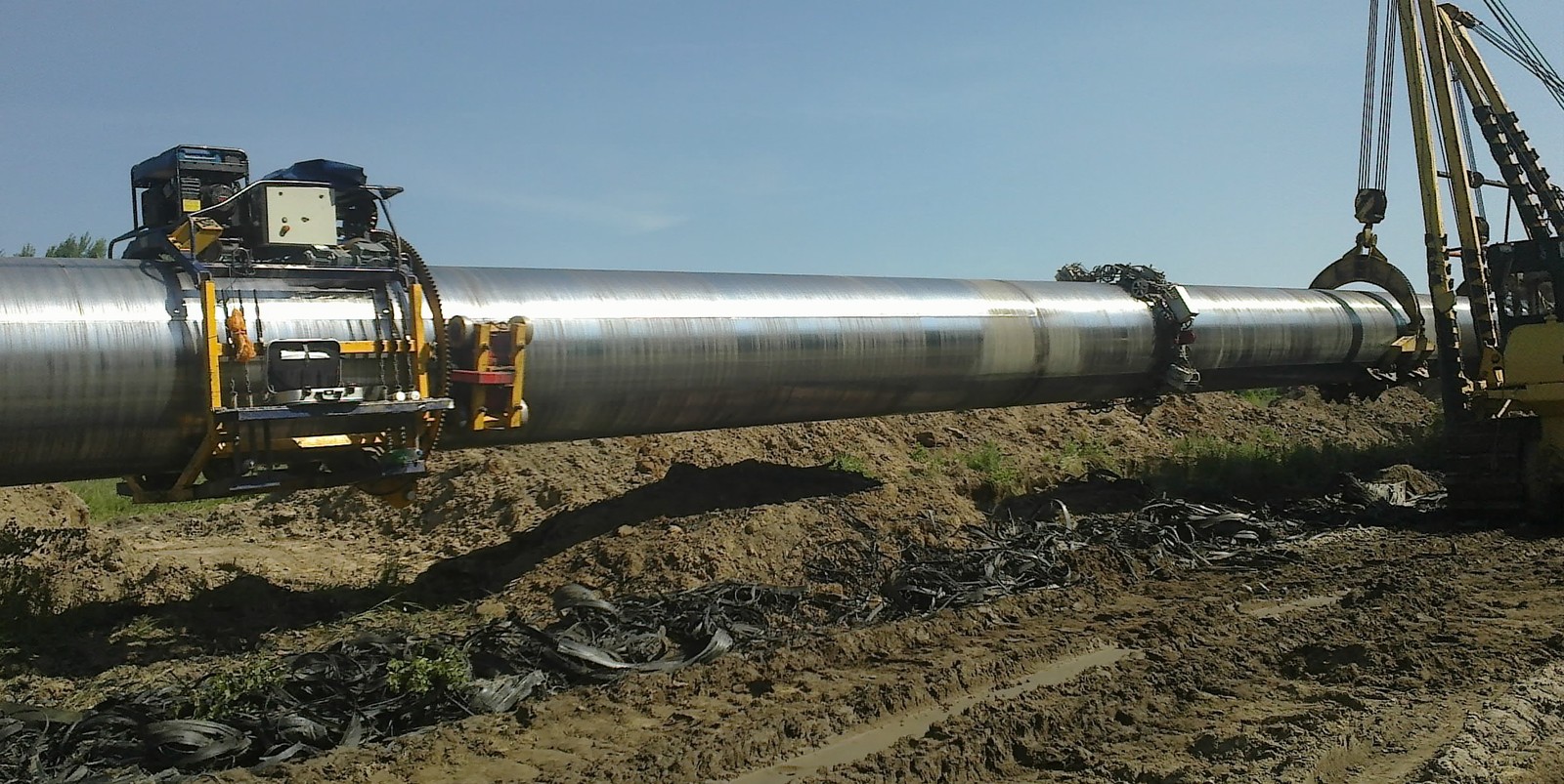
Steel pipeline and circumferential weld inspection equipment
01 · Loaded bolts

Assess the connection,
bolt by bolt.

Compare stress-state indications across a loaded bolt group to identify uneven patterns and select fasteners for closer examination. Relevant applications include turbine flanges, structural joints and pressure-system connections.

Inspection focus: relative variation, repeatability and changes after controlled intervention. Tightening torque alone does not establish uniform bolt stress.

Loaded bolts · IN-01M
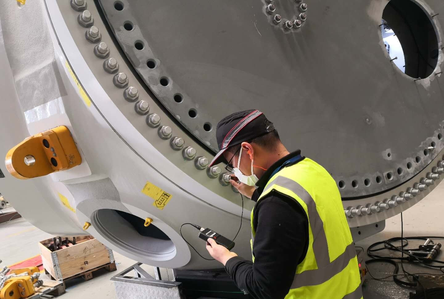
Technician taking a direct-contact measurement on a large bolted flange
03 · Loaded vessels & pipelines

Examine local stress
around critical features.

Develop an inspection plan for loaded vessels and pipelines: pressure-loaded shells, accessible pipework, nozzles, weld zones, supports and structural attachments. Compare selected locations under controlled, recorded operating conditions.

Inspection focus: local departures, feature-to-feature comparison and engineering-led verification within the operator’s pressure-equipment and pipeline integrity programmes.

Loaded vessels & pipelines
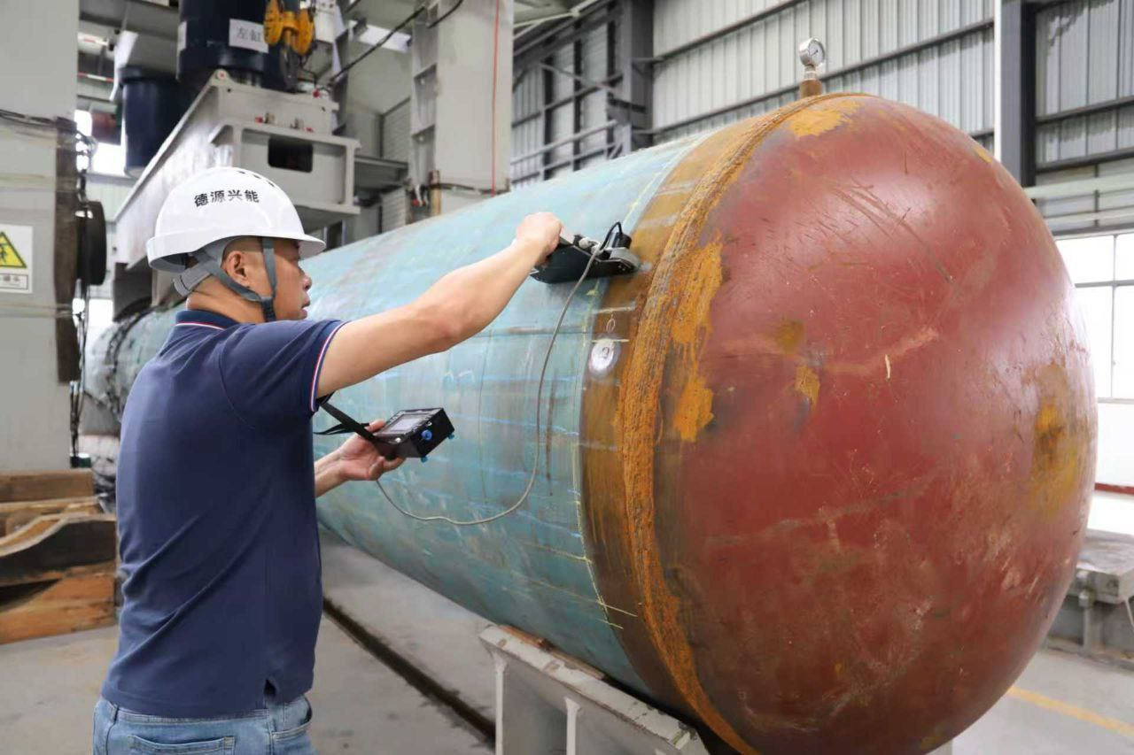
Surface inspection of a steel vessel
04 · Renewable assets

Connect flange condition
with structural loading.

Wind turbine bolt groups, tower sections and other load-bearing steel structures benefit from a consistent record of stress-state indications and changes between inspections.

Inspection focus: loaded connections, tower response and repeat inspection history. Continuous monitoring requires a separately engineered and qualified project scope.

Structural condition monitoring
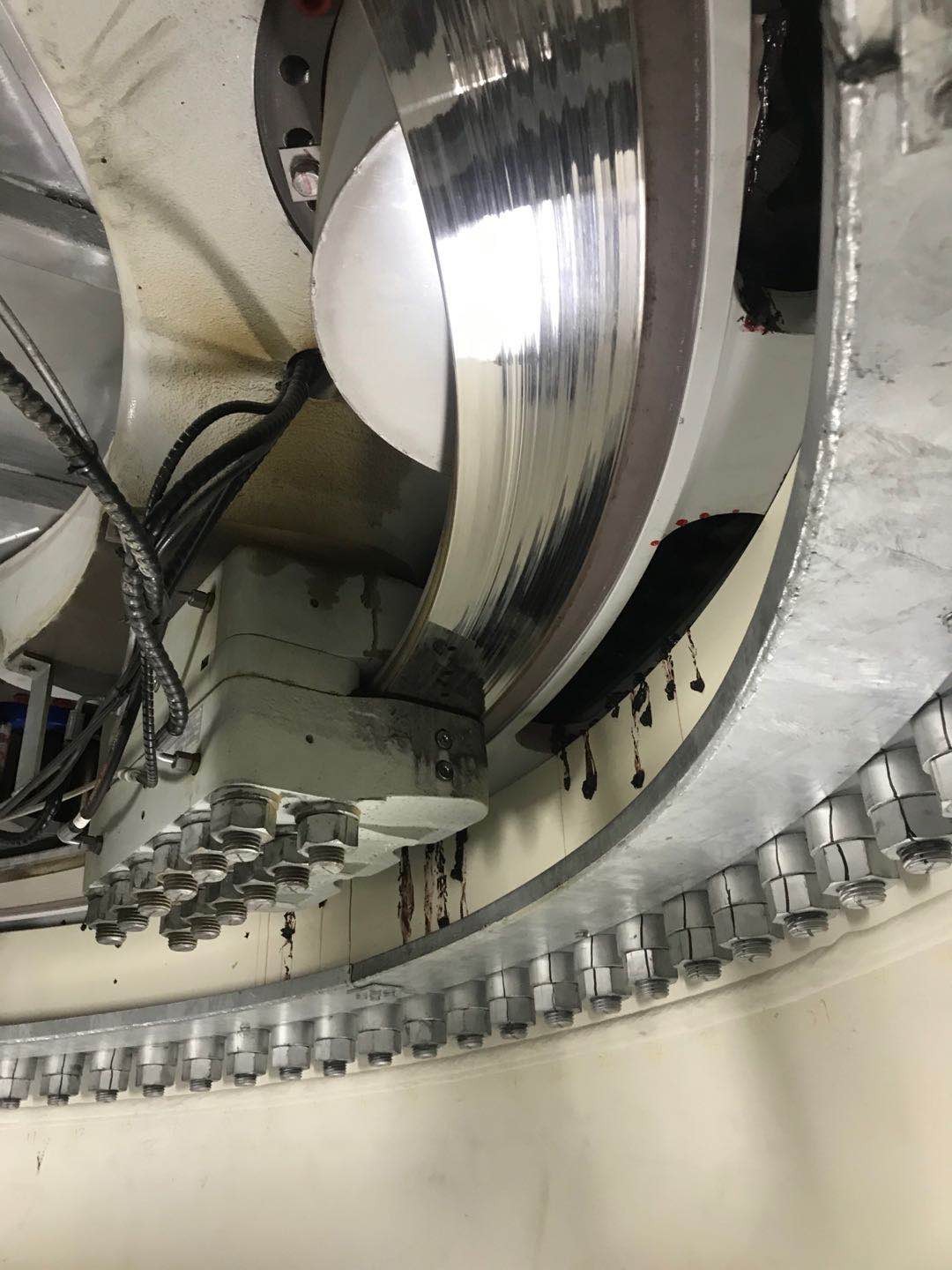
Wind turbine assembly showing load-bearing bolted connections
05 · Tank floor inspection

Map metal-loss indications.
Focus thickness verification.

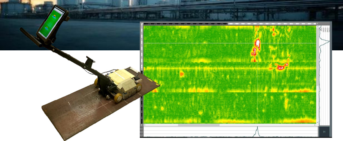
MFL scanning maps indications across suitable ferromagnetic tank-floor plates. Use the coverage record and indication map to select locations for thickness verification and detailed examination.

Inspection focus: plate condition, accessible coverage, reference checks and correlation with qualified NDT. Interpret results within the tank integrity programme.

MFL tank floor scanner
MFL tank-floor scanner and illustrative corrosion map from the manufacturer brochure
Structural Intelligence workflow

Measurement to decision.
Decision to history.

01 / Define

Asset & decision

Confirm material, loading, access, integrity threats and the engineering question.

02 / Measure

Controlled acquisition

Set reference locations and record instrument configuration and operating conditions.

03 / Investigate

Targeted verification

Review departures against geometry and service history; select appropriate follow-up NDT.

04 / Track

Condition history

Retain location-based results, confirmed findings and repeat measurements for comparison.

A complementary capability

Magnetometry.
From buried assets to wider surveys.

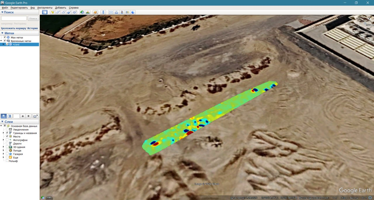
Magnetometry maps variations in the magnetic field. Ground, aerial and marine acquisition can help locate ferrous objects, investigate buried infrastructure and characterise geological features. Survey design and interpretation depend on the target and environment.

Spatial magnetic survey map along an infrastructure corridor

Oil & gas · Civil

Buried pipelines, utilities and infrastructure corridors. Combine positional data, magnetic maps and site records to choose investigation locations.

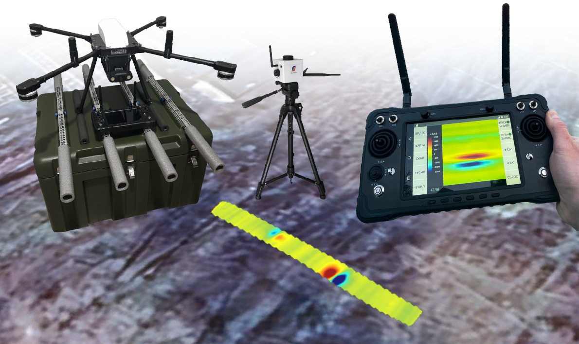
TRITON UAV magnetic mapping equipment from the manufacturer brief

Aerial · Mineral mining

Survey planning for remote or extensive areas, including geological mapping and mineral exploration. Acquisition platform and sensor configuration follow the project requirements.

TRITON UAV · Product brief
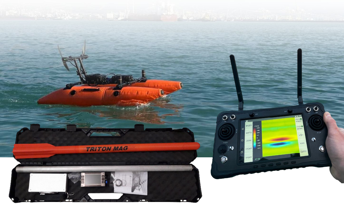
TRITON USV magnetic mapping equipment from the manufacturer brief

Marine · Defence

Magnetic mapping of submerged ferrous objects and defence-related survey applications, including unexploded-ordnance screening within specialist investigation programmes.

TRITON USV · Product brief
Buried & unpiggable pipelines

An external survey.
A focused investigation.

Where in-line inspection is impractical, a magnetic survey may provide another source of information. Assess pipe material, burial depth, route access and nearby metallic interference before selecting the method.

Download application brief · PDF
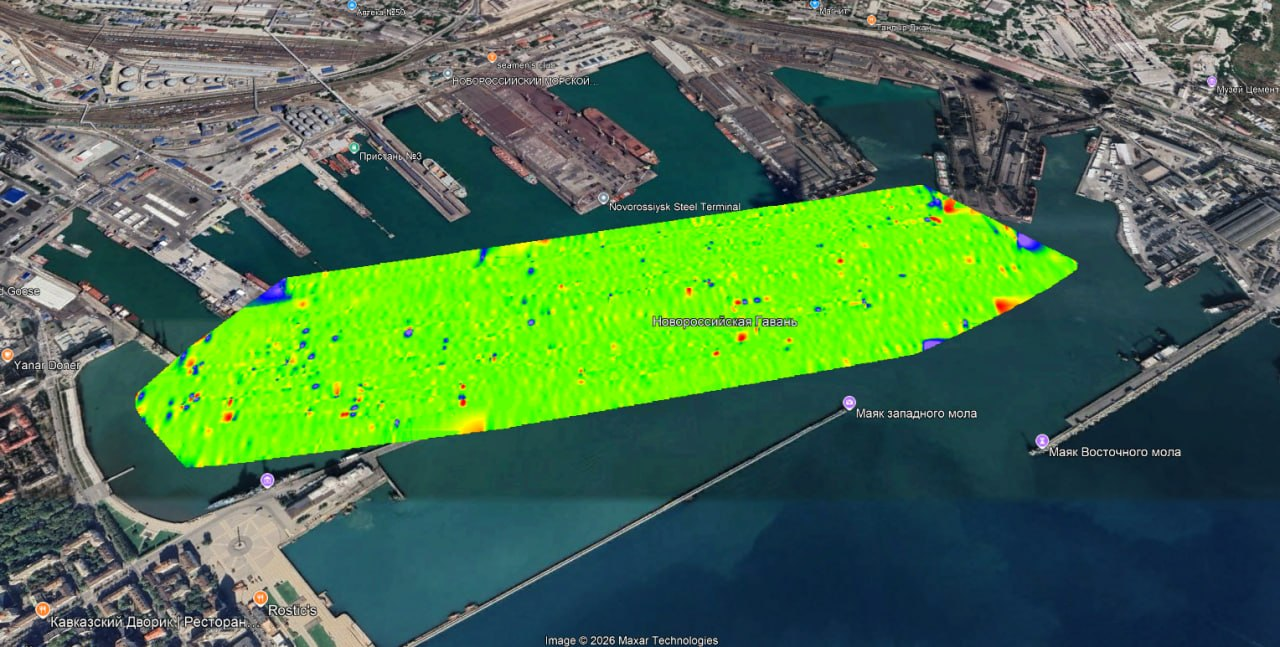
Spatial magnetic-response map overlaid on an aerial survey view

Survey maps support route investigation and feasibility planning. Anomalies require correlation and verification before they are assigned to the pipe or a damage mechanism.

Technical authority

Applications are only one layer.
Evidence connects the system.

Technology

Understand what RMF, RSD / eddy current and magnetometry actually measure, how acquisition is controlled and where each method stops.

Explore technology →

Evidence

Validation studies, field and laboratory cases, publications, patents and explicit claim boundaries — separated from commercial assertion.

Review evidence →

Insights

Engineering articles connect individual measurements with inspection strategy, prioritisation, baseline development and repeat structural history.

Read insights →
RMF · FREQUENTLY ASKED QUESTIONS

RMF complements NDT.
It does not replace it.

Screening indications guide investigation. Qualified examination and engineering review establish the findings and the integrity decision.

Does RMF replace conventional NDT?

No. Residual magnetic field (RMF) screening is complementary inspection information for suitable ferromagnetic components. It can help prioritise locations for investigation. It does not replace ultrasonic testing (UT), radiography, magnetic-particle testing, penetrant testing or other examinations required by the inspection plan, applicable requirements or OEM procedures.

What can RMF tell us?

Under defined measurement conditions, RMF screening can show relative magnetic-response patterns associated with material stress state. Bolt-to-bolt comparisons, local departures and repeat measurements can help engineers choose where to investigate. A magnetic indication is not, by itself, a confirmed defect or a calibrated load measurement.

Why use RMF if hydraulic tensioning is already used?

Hydraulic tensioning is an established assembly method. RMF does not replace or certify that process. A separately qualified RMF examination may add comparative information about the installed joint after assembly and during service. Any numerical preload assessment requires an appropriate calibration and validation for the material, geometry and instrument.

Does RMF replace OEM installation or maintenance procedures?

No. OEM installation, commissioning, tightening, acceptance and maintenance procedures remain applicable. Screening results support the engineering review; they do not authorise a change to an approved procedure.

Why inspect bolts that have already been tensioned?

Installation records document the assembly process. Seating, flange interaction, transportation, operating loads and maintenance can affect the installed joint. Repeat inspections may provide useful comparative information when the measurement locations and conditions are controlled.

Why can responses differ between bolts?

Material and manufacturing variability, residual stresses, geometry, seating, flange interaction, magnetic history and service conditions may influence a response. A different response does not automatically mean incorrect tension, a crack or imminent failure. Interpretation requires reference checks and appropriate follow-up.

How are indications verified?

Agree the inspection objective and reference locations, document acquisition conditions, review geometry and service history, then select suitable verification. This may include UT thickness or weld examination, surface examination, dimensional checks or an engineering-approved assessment of the joint. The verification method follows the suspected mechanism and asset requirements.

Can RMF confirm remaining life or fitness for service?

Not independently. Screening cannot automatically establish defect dimensions, remaining life or fitness for service. Those decisions require verified findings, relevant operating and material data, applicable assessment procedures and competent engineering review. RMF history may be an input to that process.

Is RMF screening the same as a remote magnetometry survey?

No. Direct-contact component screening and ground, aerial or marine magnetic surveys address different objectives. Buried infrastructure surveys map magnetic variations and require site-specific interpretation. Survey anomalies must be correlated and verified before they are attributed to a pipe or damage mechanism.

What should an inspection report include?

Asset and location identification; material and geometry; operating and loading conditions; instrument configuration; reference checks; acquired data and repeatability; indications and interpretation limits; recommended verification; and any confirmed findings. Keep screening indications separate from verified conclusions.

Are partner publications proof of BROT field achievements?

No. SPECTOR research, patent documents and manufacturer materials are attributed to their authors and technology owners. They provide technical context. They do not establish BROT project achievements, operator endorsement or validation for a particular asset.

Scope & reporting

Evidence for the
integrity decision.

Reports connect measurement locations, operating conditions, response patterns and recommended follow-up. Appropriate outputs include bolt-group plots, corridor maps and spatial views.

RMF screening and magnetometry

Direct-contact RMF stress screening and remote magnetic surveys serve different inspection objectives. The methods are selected and qualified for the specific material, geometry and service environment.

Acceptance and engineering review

Magnetic indications do not independently establish defect size, remaining life or fitness for service. Acceptance remains subject to appropriate verification, applicable requirements and competent engineering assessment.

Technology partners & external references

SPECTOR Sci-Tech — technical authority & technology IP owner. Our technology partner provides the underlying magnetic inspection research, instruments and methodological references. Explore its published technical work and patent documentation for the origins and development of the technology.

English patents · Science behind RMF · Citations & Publications

SPECTOR · Technical authority

TRITON — magnetometry technology partner. The TRITON website presents SPECTOR’s multichannel magnetic survey systems and their land, aerial and marine applications.

TRITON · Magnetometry technology

External publications and manufacturer materials are attributed to their authors and technology owners. They provide technical context; they do not establish BROT project achievements, operator endorsement or site-specific validation. Project reporting identifies the method, source, limitations and verification required.

Industry context

Inspection planning should fit the operator’s integrity programme and applicable guidance, including API inspection standards, ASME codes and standards and HSE pressure-system guidance. These references provide context and do not imply certification or endorsement of the methods.

Oman · GCC

Define the asset.
Set the objective.

Send the equipment description, operating conditions, access constraints and the decision you need to make. We will develop the engineering or inspection scope around your project.

Discuss your project +968 7680 3698